

2399 Splashback delay, i will be adding to this page over the following two days, as i am testing a stripboard layout and making a video for this machine.
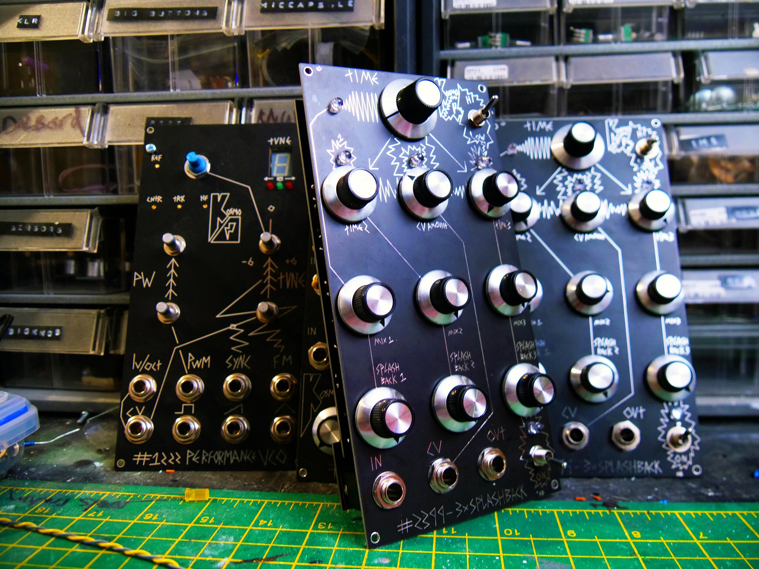
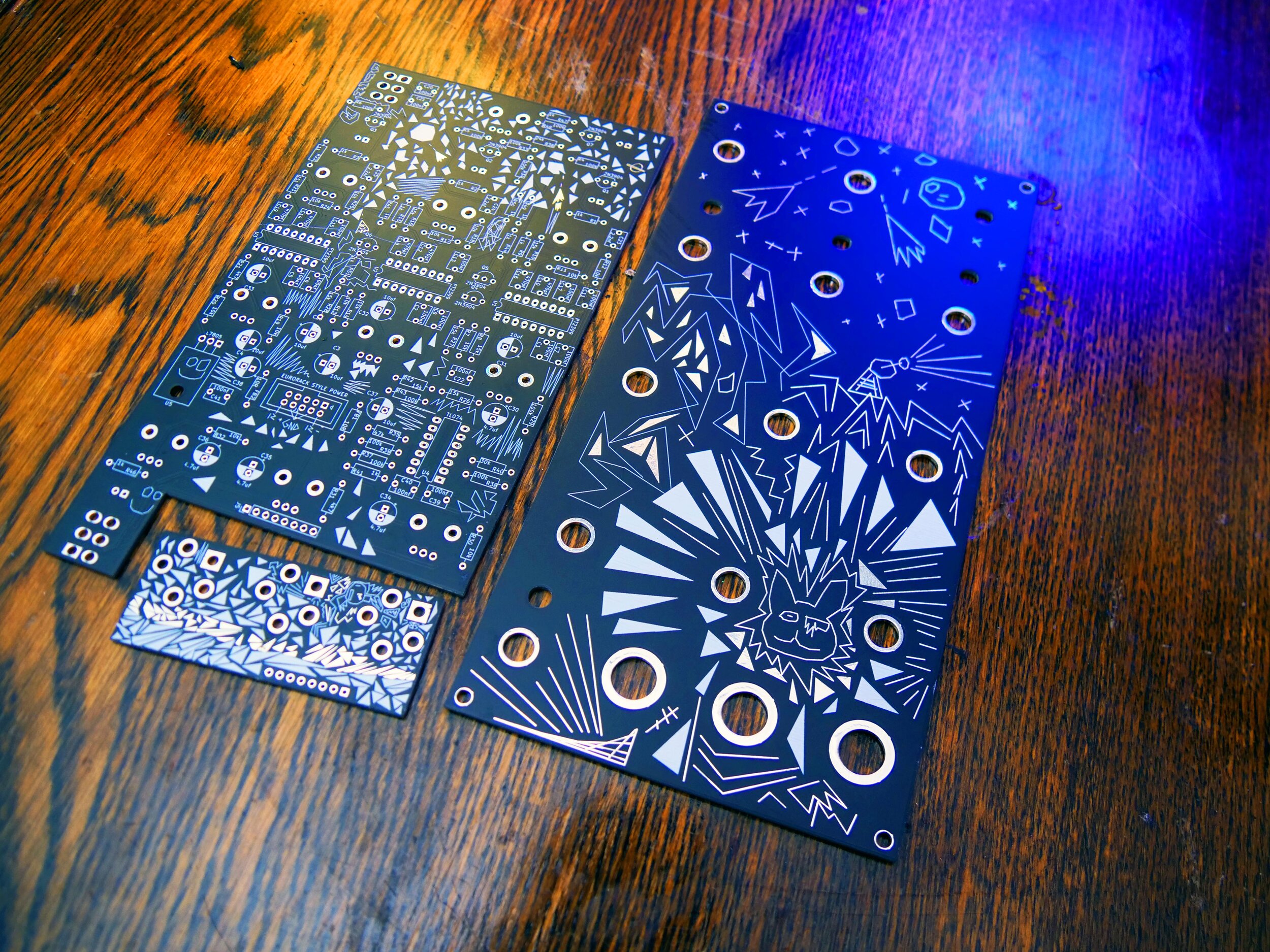
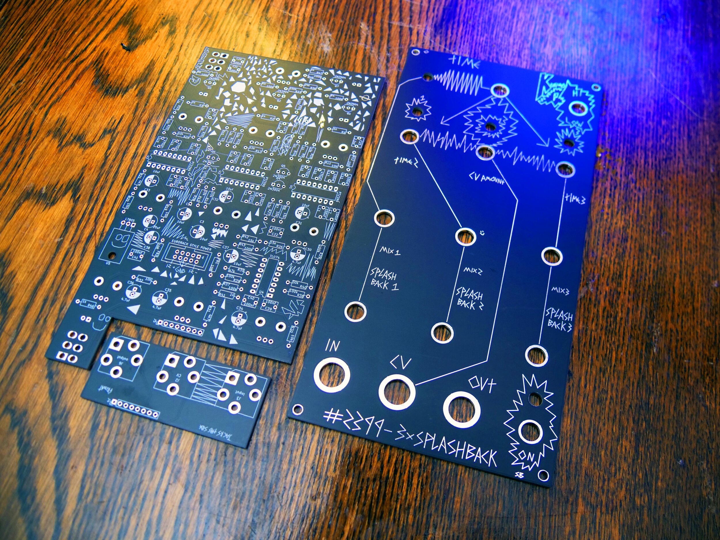
This page is about the 2399 TRIPLE SPLASHBACK DELAY available here , it is largely a triple pt2399 delay largely based on the datasheet but no stone left unturned, resulting in some sounds i haven’t heard come from a pt2399 project.


Below is the bill of materials which is a list of everything you require to build this synth module
also check out this forum page! for links that other people have found regarding components CHEAP COMPONENT SEARCH

Check in with other people building this on the 2399 forum thread *also caustic has posted for US builders links to all of the components on tayda! to make it super simple :)

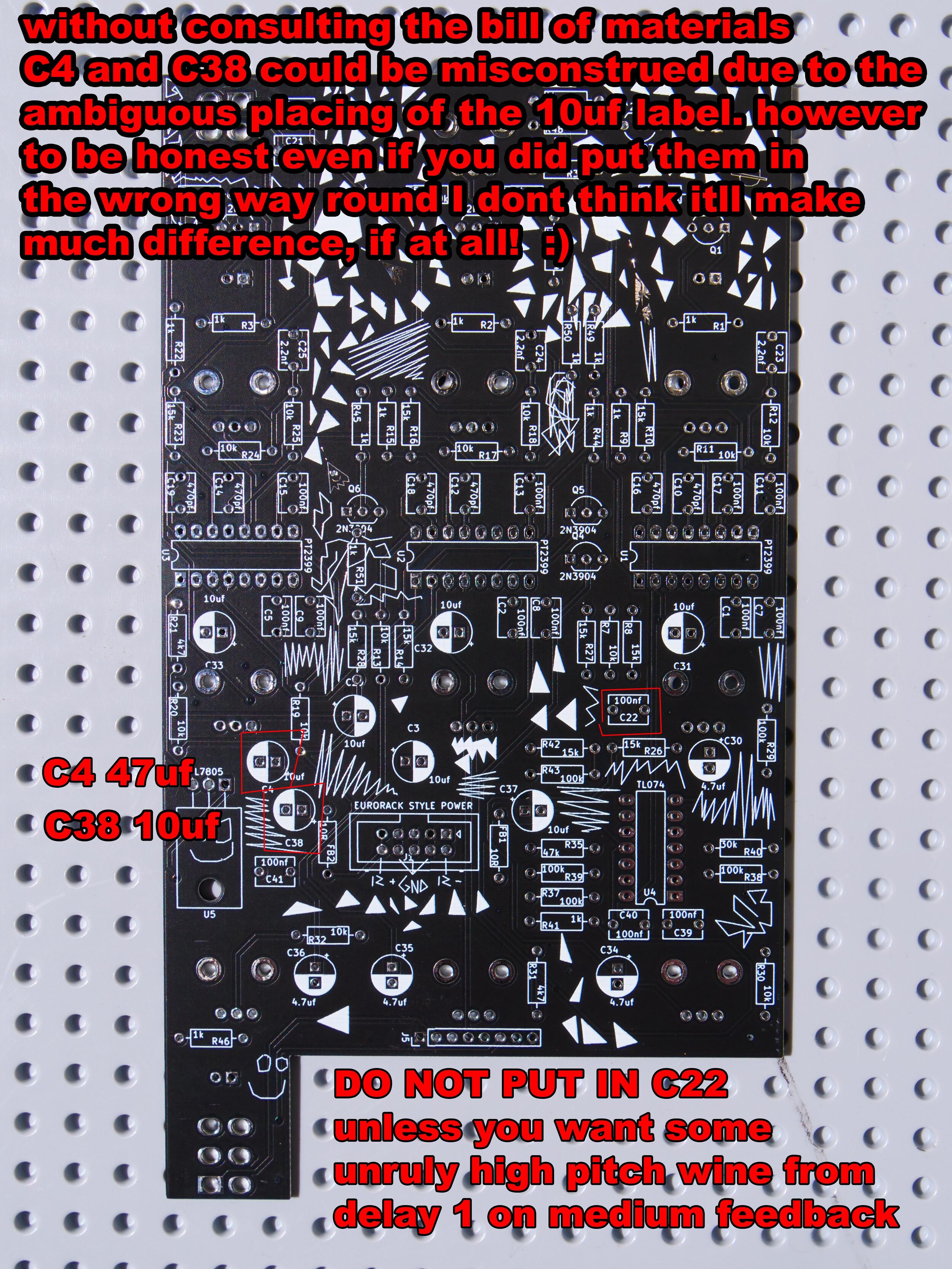
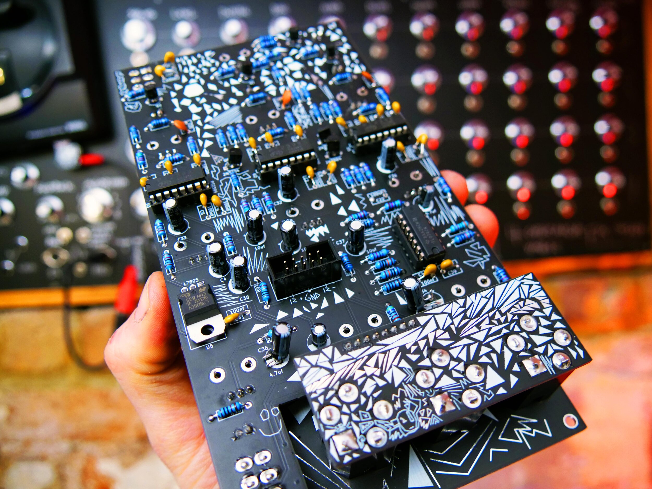
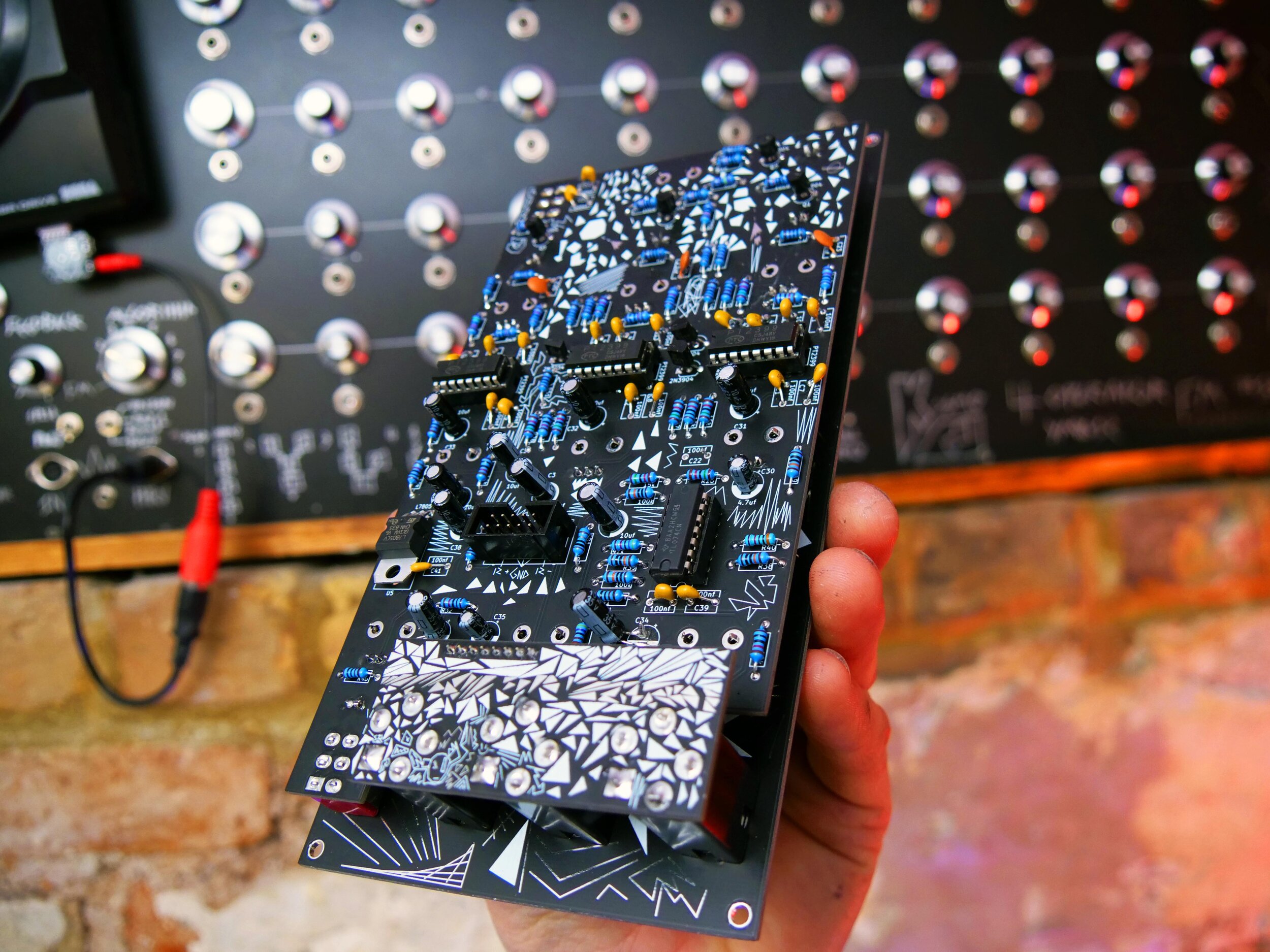
to note batch 1 (which is all of them at the minute) have 2 ambiguities, C4 is 47uf and C38 is 10uf, the 10uf label is equidistant from both footprints so if you arent soldering referring to the bill of materials you could get confused. however if you actually solder the wrong way round i don’t actually think it will make a massive amount of difference, but i haven’t tried.
Also! C22 just dont bother with it, you can put it in and try it! but it makes a very unruly feedback loop for delay 1, it makes it very hard to handle, but! you might like it. so that is up to you. but if you put it in and find feedback 1 makes it sound like putting a microphone to a speaker, thats thanks to C22.
Regarding the LED’s I like to put + signs to make it absolutely clear of the polarity, however there are many other tell tale signs of polarity so its fine without as most pcb’s dont have them but im always looking at pcb projects when im building them going “which way round is the LED” the long leg (anode +) goes into the hole that is circular, the short leg (cathode - ) goes into the square leg, there is also a flat part to the LED circle to denote that is the cathode - side.
THE CIRCUIT
So the circuit is based on the echo example schematic in the datasheet link here. (another good read electrosmash) I have made quite a few pt2399 circuits in the past, one of the first stripboard projects i did was a pt2399 delay, i have built this module as a drop in replacement for a not broken dual delay in my touring synth.
So if you know anything about the PT2399 delay which is an all in one echo processor chip, which i cant track down when it actually came out, my guess is the mid to late 80’s but if you know please enlighten me! It was designed for car stereos and karaoke machines, the idea being you had a product that needed a cheesy echo effect you would just plop in one of these bad boys.
It is a very popular chip in guitar pedals due to its low cost and low complexity, this means that it could be argued it is overused, if anything says LOFI delay, chances are! its a pt2399, from delays to cheap “analog reverbs” they probably have a pt2399. Some cheap spring reverb pedals have 3 pt2399’s hard wired into them to make a sort of swathe of 3 delays, because a reverb is in essence a more chaotic and complex echo in the real world.
Anyway because i had experience with the chip and also the fact that with multiple chips you can get a reasonably big palette of sounds, i made this module the TRIPLE SPLASHBACK.
its basically 3 delay circuits in series with a common delay time knob and 2 offset knobs to that time, so the quickest delay is the first delay and it runs into a slower one and then a slower one again. It makes a nice thick effect, it isnt the most beautiful and best delay in the world so dont expect something like that, expect a charcterful beast.
Another thing i found with the pt2399 when i built it the first time is i made a mistake and pushed it wayyyy too far out of its suggested delay time by accident, this meant that it made absolutely random garbles at the slowest extremes of the delay, right the way down to silence. this means you can make extra effects, and using it to be a standalone never repeating truly odd sound machine, it truly excels at.
DISCLAIMER, please remember a large part of my approach to these circuits is to get the most fun out of the least components. Sometimes things can get bloated, just remeber this isn’t a life support machine or a rocket navigation system, its something to make music :).
good things come in three’s
as you can see it is a modified datasheet schematic, tripled with buffered inverting inputs and outputs. simples. Hi res image
you’ll see the high low switch bypasses the second filters on the second and third delay, this makes for a swathe of high end frequencies, which immediately makes the noise sound mad and also adds an extra set of frequencies, however this will make the feedback rather unwieldy! so you need to ride this module like a horse or it wont take any prisoners!
you’ll notice the cv input is very simple, its just a mixer that mixes between the delay time knob and the CV, this then goes into some 2n3904 npn transistors which controls how much of the time pin on the pt2399 goes to ground.
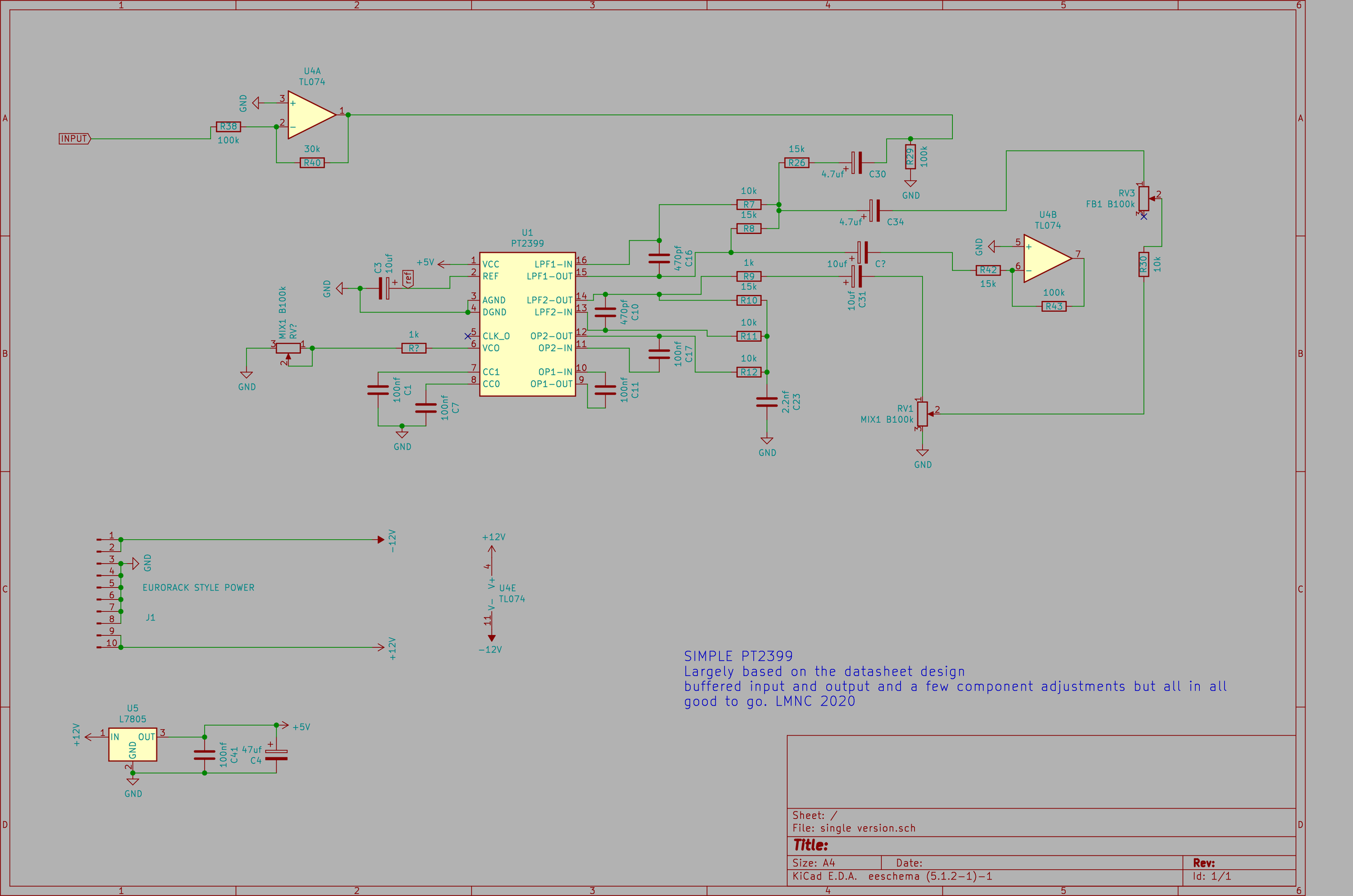
here is a simplified single delay i have drawn based on the above circuit, HI RES. it has no cv control as that makes it rather more technical. however you could pop in a vactrol to do that job. put a vactrol over from pin 1 to pin 3 of the delay time knob and see what happens.
This is a stripboard layout of the SIMPLE schematic above. this is for 1 delay. you could probably get control voltage by adding a VACTROL between pin 1 of the time Potentiometer and pin 3.
MODIFICATIONSS?S?@?!?!?!
right! so nervous squirrel over on the forum asked if there was a mod to make it completely wet. SO HERE IT IS.
to hard mod it! snip the TOP leg of R27. and to bypass wire a wire from the resistor to the positive leg of C31.
TO ADD A SWITCH TO SELECT BETWEEN NORMAL MODE AND FULL WET SIGNAL there’s a gap you can squeeze a Single pole dual throw (SPDT) mini toggle switch. be sure to get the hole in the right place (I did it by eye but was quite lucky!!!) you solder the wires like
MIDDLE LEG OF SWITCH TO SNIPPED TOP LEG OF R27.
then first leg of switch to POSITIVE LEG OF C31
then 3rd leg of switch to the pad that R27 used to be connected to.
you can swap which leg 1sr and 3rd is which depending if you want the switch to be fully wet engage or fully wet disable!
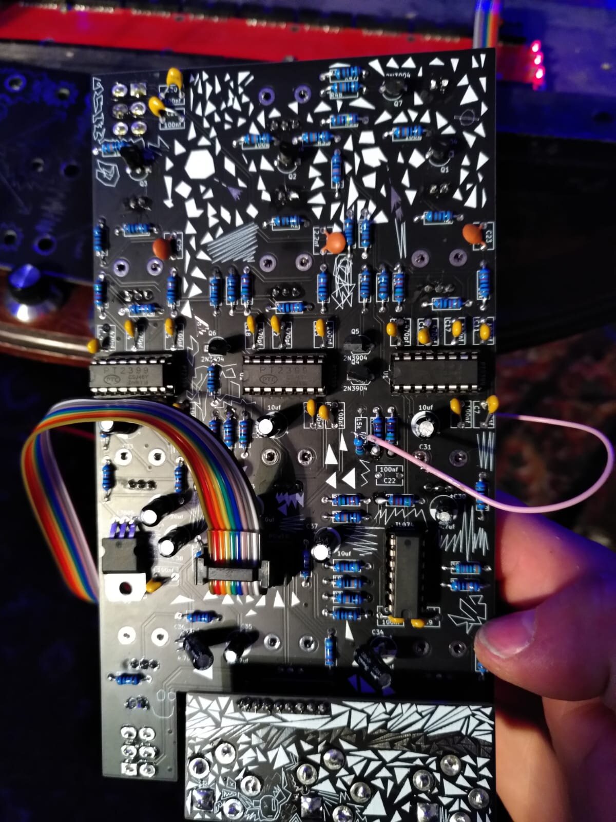

please ignore the YELLOW jumper, that was from a mod i tried and it didnt work, hence the jumper to fix the trace i cut, so ignore that. but youll see the pink wire is soldered to the +ve leg of C31

there is a gap just big enough to fit an SPDT (single pole dual throw) mini toggle switch.

i did the hole by eye and it fit! phew :D
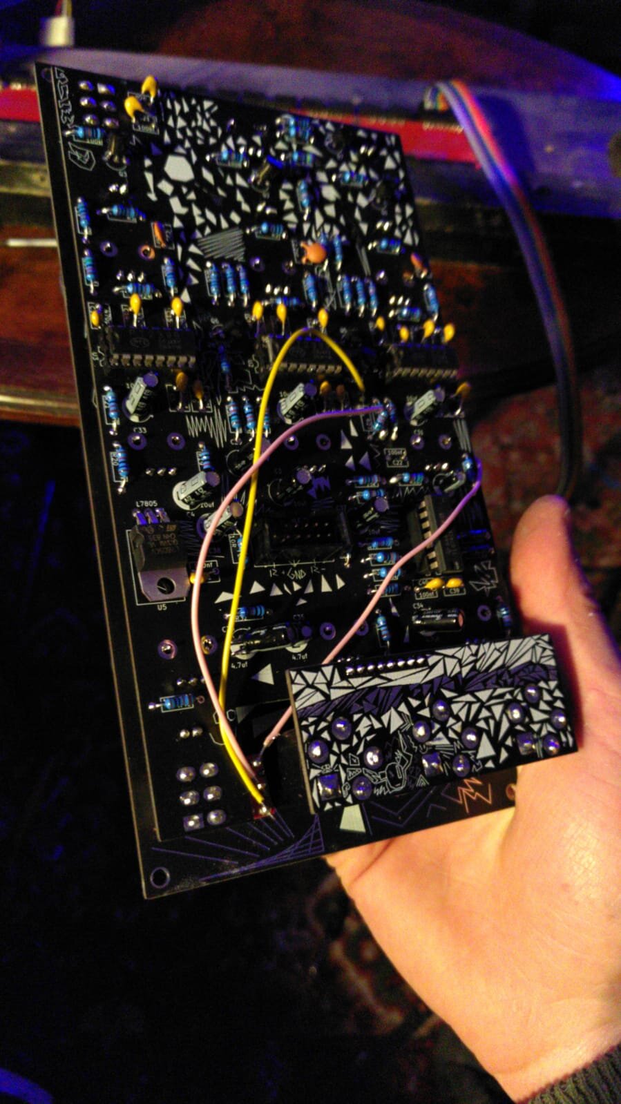
and here is the mod soldered in place. a pink wire goes from the snipped top leg of R27, and that goes to the centre pin of the switch. then a wire goes from the snipped pad of R27 (thats the yellow) to the bottom pin of the switch, then the wire from the +leg of C31 goes to the top pin of the switch, this means that you can select between normal operation and full wet mode