
Resistance (Pin 6):
Delay Time (ms):
Internal Clock Frequency (MHz):
THD (%):
As a member of the Reverb Partner Program and as an Amazon Associate, StompboxElectronics earns from, and is supported by, qualifying purchases.
Using the PT2399 Calculator
The PT2399 Echo Processor chip allows you to adjust the delay time via a simple resistor across pin 6 and ground. This calculator allows you to calculate the delay time from a resistance, or resistance from a desired delay time.


Calculating Resistance from Delay Time
Set the "Solve for" dropdown box to Resistance. Enter a delay time in milliseconds, then click Calculate.
If the resistance value exceeds 27.6k ohms, or if it falls below 5 ohms, the input box for Resistance will change from white to orange. This indicates that it falls outside of the range given in the datasheet of the PT2399.
Calculating Delay Time from Resistance
Set the "Solve for" dropdown box to Delay Time. Choose your desired resistance units (kOhms vs. Ohms) and enter the desired resistance value. Finally, click Calculate to see the resulting Delay Time in milliseconds.
Again, if the resistance value exceeds 27.6k ohms, or if it falls below 5 ohms, then the input box for Resistance will change from white to orange. This indicates that the resistance value is outside the range given in the datasheet of the PT2399.
Calculating Delay Time from Resistance
The datasheet for the PT2399 shows a table of resistance values (from pin 6 to ground), delay time, clock frequency, and THD values. That, along with the application circuits, are just about all the information you need to understand how to use the PT2399.
| R (Ω) | Clock Freq. (MHz) | Delay Time (ms) | THD (%) |
|---|---|---|---|
| 0.5 Ω | 22 MHz | 31.3 ms | 0.13 % |
| 288 Ω | 21 MHz | 32.6 ms | 0.13 % |
| 519 Ω | 20 MHz | 34.4 ms | 0.13 % |
| 723 Ω | 19 MHz | 36.6 ms | 0.14 % |
| 894 Ω | 18 MHz | 38.5 ms | 0.14 % |
| 1.08 kΩ | 17 MHz | 40.6 ms | 0.14 % |
| 1.28 kΩ | 16 MHz | 43 ms | 0.15 % |
| 1.47 kΩ | 15 MHz | 45.8 ms | 0.15 % |
| 1.67 kΩ | 14 MHz | 48.1 ms | 0.15 % |
| 2 kΩ | 13 MHz | 52.3 ms | 0.15 % |
| 2.4 kΩ | 12 MHz | 56.6 ms | 0.16 % |
| 2.8 kΩ | 11 MHz | 61.6 ms | 0.18 % |
| 3.4 kΩ | 10 MHz | 68.1 ms | 0.19 % |
| 4 kΩ | 9 MHz | 75.9 ms | 0.21 % |
| 4.5 kΩ | 8.5 MHz | 81 ms | 0.22 % |
| 4.9 kΩ | 8 MHz | 86.3 ms | 0.23 % |
| 5.4 kΩ | 7.5 MHz | 92.2 ms | 0.25 % |
| 5.8 kΩ | 7 MHz | 97.1 ms | 0.25 % |
| 6.4 kΩ | 6.5 MHz | 104.3 ms | 0.27 % |
| 7.2 kΩ | 6 MHz | 113.7 ms | 0.29 % |
| 8.2 kΩ | 5.5 MHz | 124.1 ms | 0.33 % |
| 9.2 kΩ | 5 MHz | 136.6 ms | 0.36 % |
| 10.5 kΩ | 4.5 MHz | 151 ms | 0.41 % |
| 12.1 kΩ | 4 MHz | 171 ms | 0.46 % |
| 14.3 kΩ | 3.5 MHz | 196 ms | 0.53 % |
| 17.2 kΩ | 3 MHz | 228 ms | 0.63 % |
| 21.3 kΩ | 2.5 MHz | 273 ms | 0.8 % |
| 27.6 kΩ | 2 MHz | 342 ms | 1.0 % |
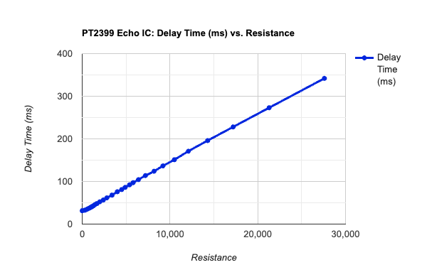
There's no equation given for the relationship between Delay Time and Resistance, but since the relationship between them is linear we can do a least squares approximation to find the line of best-fit:
The equation relating the resistance across pin 6 (in kΩ) to delay time (ms) is:

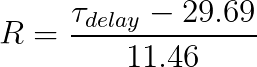
Calculating Required Resistance from Delay Time
By rearranging the equation found above, you can back-calculate and find the resistance required (kΩ) for a given delay time (ms).
PT2399 Internal Clock Frequency Calculation
The PT2399 is a digital chip. Being a digital chip, it relies on a system clock to access the internal memory registers. The clock's frequency vs. resistance is given in the table of values mentioned before.
The clock frequency has a 1/f relationship to the delay time. Well, 1/f is simple the period of the clock. So, the clock period is directly proportional to the delay time of the PT2399. Performing the same least squares approximation on that relationship yields the following equation:

Realizing that the clock period is the inverse of the clock frequency, the final equation relating delay time and clock frequency is:

PT2399 THD Calculation
The total harmonic distortion is relatively linear with the resistance on pin 6, as shown in the graph below:
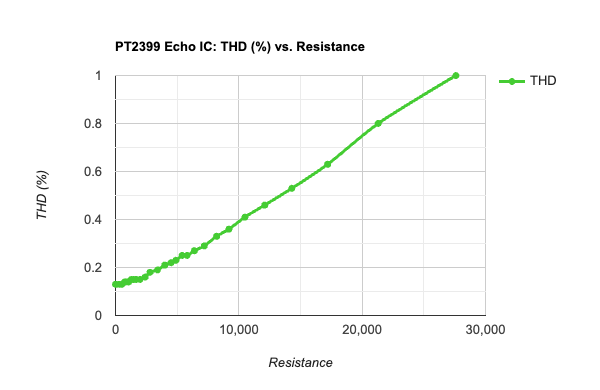
A least-square approximation gives the following the equation for calculating the THD based on the resistance:

Resources:
- Useful design equations for the PT2399 - Electric Druid (June 13th, 2015)
- PT2399 Datasheet - Princeton Technology Corp (October 2005)
- Linear Regression Calculator - Social Science Statistics
Meet the Author:

Hi, I'm Dominic. By day, I'm an engineer. By night, I repair and modify guitar effects! Since 2017, I've been independently modifying and repairing guitar effects and audio equipment under Mimmotronics Effects in Western New York. After coming out with a series of guitar effects development boards, I decided the next step is to support that community through content on what I've learned through the years. Writing about electronics gives me great joy, particularly because I love seeing what others do with the knowledge they gain about guitar effects and audio circuits. Feel free to reach out using the contact form!